Site grading is an important part of land development and civil engineering in general. Even so, site grading is not a required subject in many civil engineering programs. This means that many entry-level civil engineers must scramble to figure out grading in their first professional job after college, which is frustrating. The following blog post was written for those who are attempting to figure out site grading.
1. Follow These “Rules of Thumb”
The main objective of creating a grading and drainage plan is to “sculpt” the landscape in such a way that allows stormwater runoff leaves the site in a safe and efficient manner. At the same time, it is important to consider how people will use the site when developing your grading plan. The following rules of thumb will help you generate grading plans that accomplish these goals. Note that these are guidelines and your grading plan should always adhere to the appropriate local standards.
Concrete Grading – Concrete should not be flatter than 0.5 percent. Ideally, concrete areas should be sloped between 1.5% and 1.8%. Avoid slopes greater than 2% to minimize the chance of running into ADA compliance issues.
Asphalt and Asphalt Concrete Grading – Asphalt should not be flatter than 0.8 percent. Ideally, asphalt areas should be sloped between 1.5% and 1.8%. Slopes flatter than 1% can decrease the life of the pavement.
Parking Lot Grading – Parking lots should not have a slope greater than 4% to 5% (some developers/shopping centers have their own standards). Steeper slopes can create issues with runaway carts. Slopes steeper than 5% can also cause issues with keeping vehicle doors open when parked perpendicular to the slope.
Landscaping/Stormwater BMPs – The side slopes of stormwater BMPs and other landscaped areas should be sloped at an angle of 3:1 or flatter. Otherwise, it is difficult to mow and maintain the area.
2. Use Feature Lines To Set Up Your Grading Plan In AutoCAD Civil 3D
In AutoCAD Civil 3D, feature lines are extremely powerful tools for setting up your grading plan. They can be used as grading footprints and surface breaklines. Feature lines are easy to edit, which makes editing and revising plans simpler and more efficient. There are tools within AutoCAD Civil 3D called grading objects that can accomplish some of the same purposes as feature lines. However, grading objects seem to be more likely to cause the program to crash.
3. Adhere To ADA Requirements
It is important for civil site designers to refer to and understand the Americans with Disabilities Act (ADA) Standards for Accessible Design to ensure your site complies with these legal requirements. Some examples of ADA requirements for grading and drainage include:
- The maximum cross slope in any accessible area is 2%.
- Doors must have a level landing. This means (conservatively) that adjacent concrete should be sloped at a maximum angle of 2% within 5 feet of any part of an outward swinging door and 4 feet from an inward swinging door. Refer to ADA Guidelines 404.2.4.1 for more detail.
- The maximum slope of the path of travel is 12:1 (8.33%).
- No ramp may rise more than 30 inches before a landing.
- The concrete adjacent to a door must be within ½ inch (0.04 feet) of the floor at doors if it is an ADA-accessible door.
4. Understand Standard Annotations
When drafting a grading and drainage plan, it is important to understand how your plans should look and what information needs to be communicated. The best way to do this is to find some previous examples of solid site grading. Ideally, these examples should be provided by your company so you can get a feel for their drafting standards and design standards. Study these examples and stare at them for a while before starting work on your own site grading. Then, as you progress through your first couple of projects, refer back to these examples frequently. Eventually, you will develop a process that works best for you!
Although each company is different, there are standard annotations that you will find on almost all grading plans. The following image shows some examples of these annotations.
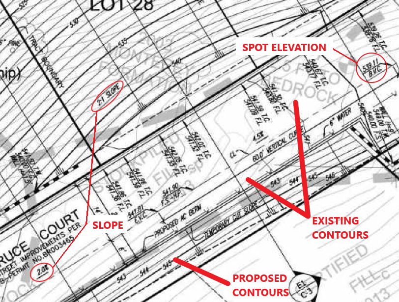
Spot Elevations – Spot elevations on a grading plan depict the exact elevation of a point on the existing or proposed surface. Typically, spot elevations are shown to the nearest tenth (0.1′) or hundredth (0.01′) of a foot.
Contours – Contour lines connect points of the same elevation. Contour lines should never intersect and should always close. Existing contour lines are typically shown as dashed lines and are often shown in a lighter color. Proposed contour lines are typically solid lines with heavier line weights.
Slopes – It is important to show slopes on your grading plans when a portion of your site design must adhere to ADA requirements. In addition, the steepness of features such as basin side slopes should be noted. If the slope is flatter than 0.1 ft/ft, slopes should be labeled as a percent (e.g., 10%). Slopes steeper than 10% should be labeled as the ratio of horizontal distance to vertical distance (e.g, 3:1, 4:1).
5. Pay Attention To Setbacks
Setbacks are important when deciding where landscaped areas or stormwater BMPs will go on your site. In general, you want rain gardens or any other feature that will hold water at some point to be placed at least 10 feet away from building foundations and property lines. Ideally, they should also be placed at least 3 feet away from hardscape or public right-of-ways. Note that these values are rules of thumb based on my experience in my specific geographic area (Southern California). Check your local regulations to determine whether these setbacks are appropriate for your design.
6. Ensure the Benchmark and Vertical Datum Is Noted On The Plans
Always indicate the benchmark and vertical datum (e.g., NGVD29 or NAVD88) on your plans. In some areas, the orthometric height difference between NGVD29 and NAVD88 is in excess of three feet! For this reason, it is essential to clearly define the vertical datum your plan is referencing to ensure that your drawings make sense with drawings being prepared by other consultants. It also helps avoid confusion and frustration if someone needs to refer to your drawings a couple of months (or years) later.
7. Balance Cut and Fill If Possible
Import and export of earthwork materials can be quite expensive. For this reason, it is best to balance cut and fill volumes if possible. This is particularly true if you are working on a residential project. Realistically, it is fairly easy to move a bit of dirt around a site to avoid importing or exporting dirt to the site. For this reason, a 0.1 to 0.2-foot depth of earthwork quantity imbalance across the grading area is acceptable. When performing earthwork quantity estimates, estimate the following.
- Cut and fill – this can be estimated in AutoCAD Civil 3D by generating a volume surface to estimate cut and fill by computing the difference between the base surface (existing ground) and the comparison surface (finished ground).
- Extra cut required for a building pad, concrete walkway, landscaping, or other similar construction work.
- Dirt loss – Ideally, the engineer would have a geotechnical report that provides a compaction estimate. However, that is often not the case. This means it is impossible to provide an exact estimate of dirt loss. Something around 0.1 feet is appropriate if there is no compaction estimate.
8. Use Layer Names That Make Sense
Your drawings will look much more professional to other engineers if you use layer names that follow common naming conventions. If you live in the United States of America (USA), I strongly recommend following the American Institute of Architects (AIA) National CAD Standard. According to this standard, layer names begin with a prefix associated with the discipline associated with the work that will be depicted by that layer. Subsequent segments of the layer name are to be exactly four characters in length and separated by a hyphen.
- The layer name should begin with the discipline associated with the work that will be depicted by that layer. The following table lists some common examples of discipline designators.
| Designator | Description |
|---|---|
| A | Architectural |
| C | Civil |
| E | Electrical |
| L | Landscape |
| P | Plumbing |
| V | Survey/Mapping |
2. The next segment of the layer name is referred to as the major group. This document contains a list of the major groups used when naming layers according to the AIA standard. Some examples of segments you will see in this group are listed in the following table.
| Designator | Description |
|---|---|
| ANNO | Annotation |
| BLDG | Building |
| BNDRY | Boundary |
| ESMT | Easement |
| PIPE | Pipe |
| PVMT | Pavement |
| ROAD | Road |
| STRM | Storm Sewer |
| TOPO | Topographic Feature |
| WETL | Wetland |
3. The next parts of the layer name are referred to as the minor groups. Everything after the major groups is up for grabs as long as the abbreviation makes sense, and the segments are four characters long. In some cases, a suffix is added to the end of the layer name to indicate the phase/status of the work being depicted by that layer. Some examples of suffixes include E for existing, F for future, T for temporary, and N for new.
9. Refer To Standard Details and Specifications
When preparing grading and drainage plans, it is important to include references to standard details and specifications for common features such as curbs, backflow preventers, sidewalks, or paving. These standard details and specifications are typically published by local governments, the county, or the Department of Transportation (DOT).
10. Avoid Large Retaining Walls
Retaining walls are used to address steep slopes on a site. If possible, avoid retaining walls that are taller than 3 to 4 feet in height. Retaining walls higher than this typically require a structural or geotechnical engineer. It is also important to remember that retaining walls are typically more expensive than natural grading, so minimize their use of them on a site. Finally, it is worth noting that many modular retaining wall vendors will provide signed and sealed calculation and drawing packages if you use their product for a project.
11. Bonus Tip: Get Really Good at AutoCAD Civil 3D
Many engineers do not want to spend their whole careers drafting every day. For this reason, some people resist drafting in an effort to avoid being siloed into AutoCAD work. While I understand this sentiment, I am of the belief that you should get as good as you can at AutoCAD early in your career. A solid background in AutoCAD Civil 3D will make your professional life much easier and you will communicate more effectively with drafters as you progress in your career. While AutoCAD may not be the most exciting topic for some, I do recommend committing to attending some training workshops and/or watching YouTube videos that will enhance your understanding of the program.