I have been using HEC-RAS for many projects and at several companies. Throughout my experience as an HEC-RAS user, I have learned how to develop hydraulic models more accurately and efficiently. There are many things I know now that I wish I could tell my younger self when she was struggling through her first hydraulic modeling projects. This blog post outlines some of the lessons I have learned “the hard way.” Hopefully, at least some of these tips will save you some time and frustration.
1. Georeference every model
Georeferencing establishes the relationship between an object and a particular coordinate system. With the addition of RAS Mapper in newer versions of HEC-RAS, it is now easier to georeference hydraulic models. The benefit of a georeferenced model is that you can overly the cross-sections on aerial imagery. This will help you develop more accurate hydraulic models because you will be able to check whether you have drawn your cross-sections appropriately and placed your bank stations in the right places. You can also verify that your topographic data makes sense. A georeferenced model also allows you to export model results and add them to maps and exhibits.
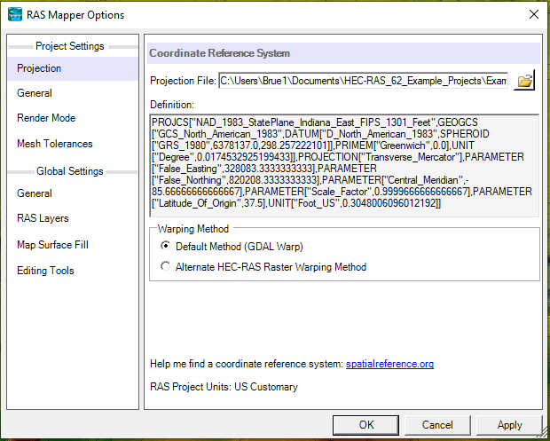
In order to georeference a model, open the RAS Mapper. Then click Tools and select Set Projection for Project. A dialog box will appear (see image below). Click the folder icon on the right side and navigate to the appropriate ESRI projection file, which is usually associated with a shapefile). Make sure that you select a projection file and not an HEC-RAS project file. In HEC-RAS version 6.2, set the projection file by clicking Project at the top menu and selecting Set Projection. The image below depicts the dialog box used to set the projection for your HEC-RAS model.
2. Write descriptions in HEC-RAS
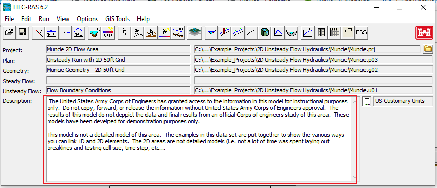
Writing a description of your model is also important because you never know when you will need a model again. You may think that you will remember the details of a particular model, but it is amazing how many details you forget after working on other projects. I suggest taking a few extra minutes to describe the purpose of your model, the purpose of every geometry file (e.g., existing, design alternative 1, design alternative 2, etc.), the topographic data used to cut cross-sections, where your flow rates came from for the flow data, and any other pertinent information. This could save your future self (or others) a lot of time and headache. A description will also help your client (or governing agency) review your model more efficiently.
3. When setting up a 2D HEC-RAS model, start with larger cell sizes and short simulation times
At a previous job, I created many HEC-RAS 2D models for dam breach inundation studies. These models could take several hours or even a couple of days to run. You can imagine my dismay when I would see an error message after waiting over 24 hours for a model to finish running. This was a very inefficient way to debug a 2D HEC-RAS model. I was (unrealistically) trying to produce the final model the first time I pressed “Run.” After a while, I figured out that initially running the model with a 2D flow area containing larger cells would allow me to find and fix errors more quickly. The final cell size will on a variety of factors such as the spatial resolution of the terrain and the steepness of the terrain. As you develop your model, decrease the cell size until your error is acceptable. Remember that you can use breaklines to refine your 2D mesh in select areas such as along a ridge, levee, or roadway.
In addition, I recommend running your model for a shorter time when you are initially setting up the geometry. For example, when you run your model for the first time, your simulation time should range from one hour to six hours. As you refine your model, increase the simulation time.
It is worth noting that newer versions of HEC-RAS (version 6.1 and 6.2) run much faster than some of the older versions.
4. Check the volume accounting error (2D)
Another thing I have learned about 2D modeling is the importance of checking the volume accounting error. Even if your results make sense, your volumetric error may tell a different story. In my experience, a significant volume accounting error indicates that flow has made it to the boundary of your 2D flow area and has no means of escaping. I would recommend inspecting your 2D flow area carefully and expanding it in areas where water touches the boundary. A large volumetric error may also be an indication of an error in how you set up your boundary conditions.
To check the volume accounting error, check the Computational Log file by opening the Unsteady Flow Analysis dialog box, clicking options, and clicking “View Computational Log File.” An example of a computational log file is shown below. The volume accounting error has a red box around it.
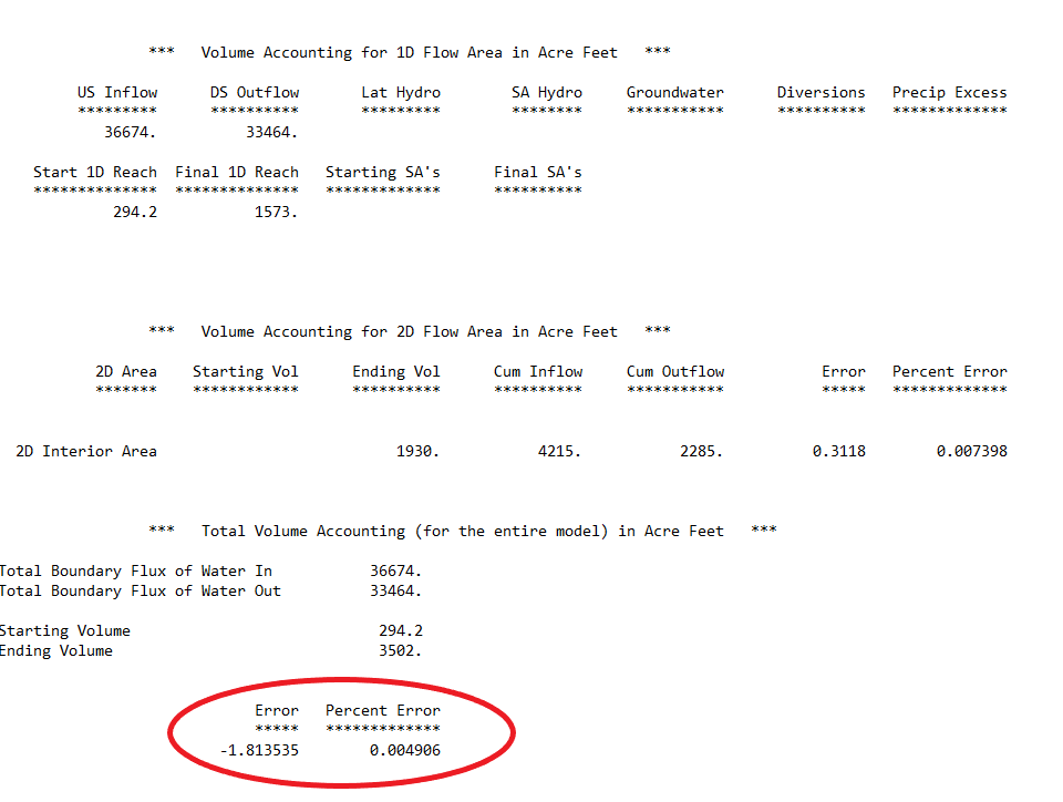
Typically, your volume accounting error should be less than 1% (0.01). However, a higher volume error is probably acceptable if you are running a dam break model or a 1D/2D model.
If you have a very large volume accounting error, I recommend inspecting your mesh to see if there is a “leak.” If you find a leak, either make your mesh larger or add a boundary condition line that allows the flow to leave the system.
5. Debug one error at a time
Another strategy for developing HEC-RAS models more efficiently is to work on debugging one error at a time. If you run a model and find there is a long list of convergence errors, work on one error at a time. Otherwise, you may create more errors or find it difficult to keep track of what you are modifying. However, if you debug one error at a time, you can “undo” a particular modification if does not fix any problems.
6. Keep track of your reach lengths (1D)
For each cross-section, HEC-RAS requires that you enter the downstream reach lengths for the channel, left overbank, and right overbank. During the process of developing a hydraulic model, you may import additional cross-sections or get rid of cross-sections. During this process of model development, it can be difficult to keep track of what reach lengths have been modified/updated to reflect such changes. This is particularly true when you import GIS data because the reach lengths will change when you import them. I find that recording reach lengths in a spreadsheet helps keep track of the measured reach lengths.
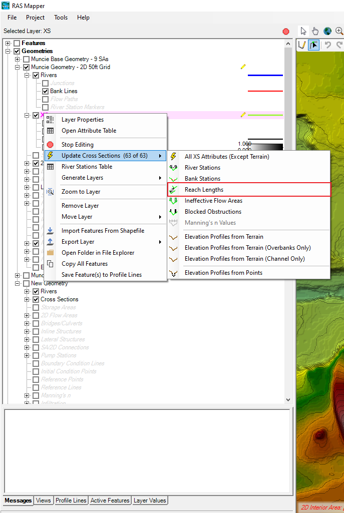
Downstream reach lengths can be automatically calculated in RAS Mapper. You need to draw bank lines in RAS Mapper. Simply right-click XS in the RAS Mapper contents window. Then select Update Cross Sections and Reach Lengths.
7. Topographic data does not always reflect reality
After cutting cross-sections from topographic data, it is important that you check the data. This is because there are several sources of error when collecting LiDAR data such as errors due to GPS sensor position and errors due to the laser instrument not being perfect with the aircraft. Examine each cross-section to make sure it captures major topographic features. I would also recommend measuring the channel top width and comparing it to the channel top width depicted in the model.
In addition to errors in data collection, there is often a significant amount of noise associated with cross-sections cut from LiDAR data. This is especially obvious when cross-sections are cut from a topographic dataset with a coarse spatial resolution.
You can eliminate some of this noise by removing some points. However, removing points is only required if a cross-section contains more than 500 points. In this case, you can manually delete points, or you can use the cross-section filter.
8. Perform a sensitivity analysis
The purpose of a sensitivity analysis is to determine how different values of a parameter impact the results of the model. A sensitivity analysis is an important aspect of hydraulic modeling.
For example, I recommend that you conduct a sensitivity analysis to demonstrate that the boundary condition you have selected does not impact the results in your study area. This would involve running your model again with a different boundary condition (e.g., critical depth). Compare the results of this run to the run with your original boundary condition and verify that the results are the same in the area of interest. If you are running a subcritical model, this proves that your model extends far enough downstream.
Note that if you are running your model with the mixed flow regime, you will have to perform sensitivity analyses for the upstream and downstream boundary conditions.
Another common exercise is to perform a sensitivity analysis to determine how different Manning’s n values impact the hydraulic results. In general, higher Manning’s n values will result in lower flow velocities and higher water surface elevations. In contrast, lower Manning’s n values will result in higher flow velocities and lower water surface elevations.
9. Use the “Compare Geometry” feature available in the Cross Section Viewer
The purpose of many HEC-RAS projects is to determine how the hydraulic results will change due to the construction of a project. This often involves preparing two geometries: the existing conditions geometry and the proposed conditions geometry. The Compare Geometry feature available in the Cross Section Viewer allows you to look at these geometries at the same time.
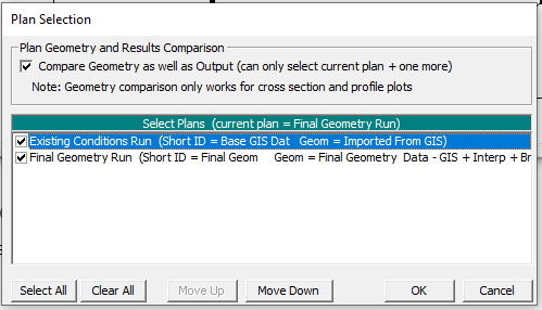
To compare geometries, open the Cross Section Viewer by clicking View at the top menu of the main HEC-RAS window. Then select Cross Section. In the Cross Section Viewer, click Options then Plans. A dialog box below will open. Then make sure that the box at the top (Compare Geometry as well as Output) is checked. Next, select the plans you would like to compare. It is important to note that the geometries you wish to compare need to be associated with a specific plan. An example is shown in the image below. Finally, click OK.
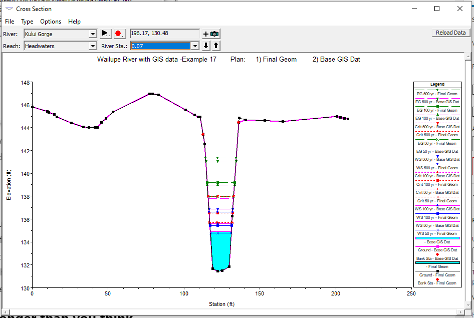
After clicking OK, the following image will appear. The geometry associated with the plan listed first in the image above will be shown in black, and the geometry of the geometry listed second will be shown in pink.
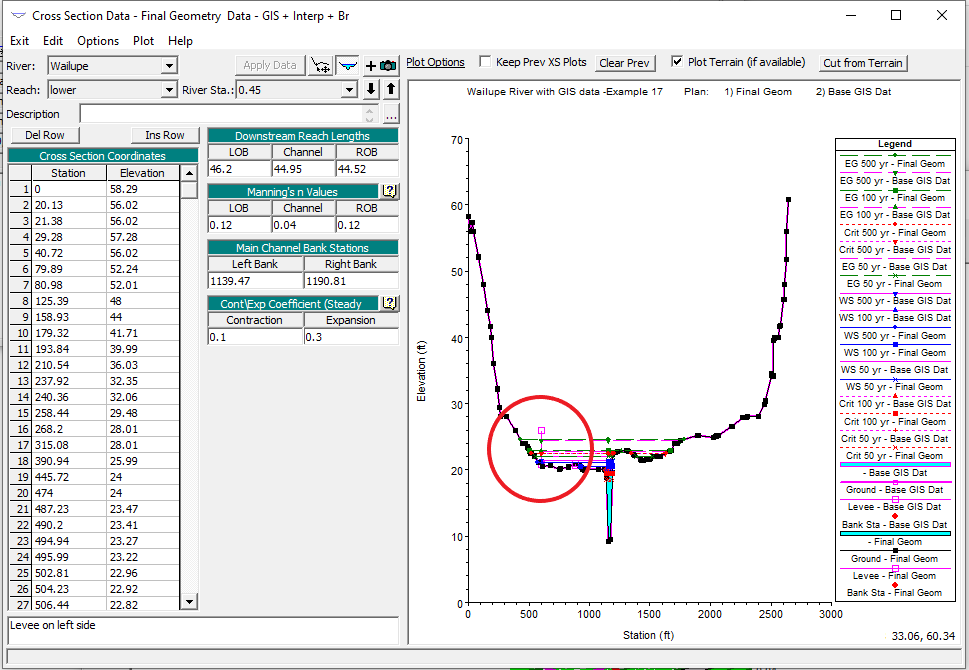
It took me a while to appreciate the value of this feature, but using the cross-section viewer is much easier than opening two models. If you find that the cross-sections for the two plans are not lining up properly, I recommend checking the cut lines. Make sure the cross-section length (last station minus first station) is the same as the cut line length. If they are not, update the cut line coordinates so they accurately reflect each cross-section’s geospatial location.
10. Everything will take longer than you think
When you are communicating how long a particular hydraulic modeling task is going to take, remember that everything always takes longer than you would expect. Unexpected problems always seem to pop up when preparing a hydraulic model. Examples of such problems include computer issues, uncertainty regarding the vertical datum for the topographic data, lack of information, incorrect information, or unforeseen instability problems (this is particularly true for unsteady models).
For this reason, it is important that you give yourself enough time to address any unforeseen problems.
11. Understand when to use ineffective flow areas and levee markers
It is important to understand when to use ineffective flow areas and levee markers. Note that this tip is only applicable for 1D modeling. Ineffective flow areas and levee markers are used to better define how flow will move through the channel or stream.
Ineffective Flow Areas
Ineffective flow areas are used to define areas in the cross-section where the flow will NOT be actively conveyed (flow velocity is close to zero). In other words, these are areas where water will pond rather than continue to move through the stream.
To define ineffective flow areas, navigate to the Cross Section Editor. Click Options then Ineffective Flow Areas. A box like the one shown below will pop up. Fill in the applicable fields. Ineffective flow areas will be represented by green lines.
When you use a normal ineffective flow area, you must define a left station and elevation as well as a right station and elevation for the ineffective flow area. When you use the normal ineffective flow area, the areas to the left of the left station and to the right of the right station are considered ineffective when the water surface is below the entered elevation.
Another option is to enter multiple blocks of ineffective flow area. This requires that you enter a left station, a right station, and an elevation for each block. Once the water surface elevation is higher than the elevation entered, the blocked area is no longer considered ineffective.
When you make an ineffective flow area “permanent,” the defined area will still be considered ineffective even when the calculated water surface elevation is above the defined elevation.
Levee Markers
Levees allow you to constrain flow within an HEC-RAS cross-section. Otherwise, HEC-RAS assumes that flow can go anywhere within the cross-section. To add a levee marker, click Options in the Cross Section Editor. Then click Levees. A box like the one below will appear. Enter the appropriate values into the boxes. Water will not be able to enter the area to the left of the left station or to the right of the right station.
12. Hydraulic modeling is a science and an art
Remember that hydraulic modeling is a science and an art. This tip is more philosophical on nature, but I have seen some engineers get hung up on what is “right” and what is “wrong.” There are certainly incorrect ways to model hydraulic structures, but there are also a number of ways to model hydrology and hydraulics correctly. Essentially everything associated with the natural world is uncertain.
All models are wrong, but some are useful.
George E.P. Box
When working on your model, it is important to do the best you can with the information and resources you have. This does not mean you should not spend too much time agonizing over tiny details that will not impact the overall results. For example, spending several hours deciding whether you should apply a Manning’s n of 0.013 or 0.014 is a waste of time because this difference will probably not impact the results. If you are unsure whether a particular parameter will significantly impact the model results, perform a sensitivity analysis (see Tip No. 8).
13. Make sure your model results make sense
This tip applies to many aspects of engineering. Always make sure your model results make sense. It can be easy to turn in a model after meticulously determining every parameter and piecing together the geometry. Scroll through the cross-sections and look at the profile view to make sure that your results are not drastically different than what is expected.
Learn More
If you have started using HEC-RAS and want to learn more about 1D modeling, check out the Australian Water School and Full Momentum on YouTube. This course will walk you through the basics of modeling in HEC-RAS with a series of lectures and projects that will allow you to apply your new skills.