Cut lines are an important aspect of georeferenced HEC-RAS models because they represent the geospatial location of your cross sections in plan view. If you are having issues with the placement of your cross sections, I recommend looking at the cut lines table. The following blog post will describe how to use the cut lines table to verify that the geospatial length of your cross sections matches the model length (stationing) shown in the Cross Section Data Editor.
The Cut Lines Table in HEC-RAS
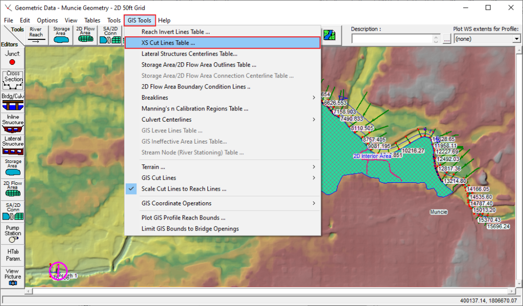
To navigate to the cut lines table, click GIS Tools in the Geometric Data Editor. Then select XS Cut Lines Table. In the image below, you may also notice that the Scale Cut Lines to Reach Lines option is checked, which is the default in HEC-RAS. This option is useful when your geometric data is not georeferenced. However, it is best to turn this option off when your geometry is georeferenced so that you can view your geometry in a geospatially correct way.

If an HEC-RAS model is georeferenced, the cut lines table will show the coordinates of each point within each cross section as shown below. Simply use the arrows next to the River, Reach, and RS (River Station) boxes to cycle through your cross sections. The numbers in the Schematic X and Schematic Y columns are the x and y coordinates of each node of the cross section as shown in the image below.

If your cross sections are not georeferenced, they will show up as straight lines. In this case, the cut lines table will appear like the image below. There will be no data in the Schematic X and Schematic Y columns, and (NO DATA !!!!) will appear next to the river station number.

Verifying that the geospatial length of each cross section matches the modeled length
Accurately presenting information depicting the data used to run a model can be almost as important as the model itself, especially if the model is being reviewed by a client or regulatory agency. After all, how can others interpret your model results with confidence if they do not have an accurate understanding of what you are trying to represent in a particular HEC-RAS model? This means that it is important to verify that you are accurately depicting the location and length of each cross section in your exhibits and maps. One way to do this is to check the cross section lengths.
The modeled length of each cross section, which can be computed by subtracting the first station from the last station, should be the same length as the cross section lines shown in RAS Mapper. This is important because the cross sections shown in RAS Mapper are often exported as a shapefile and used to create a cross section location map. If the cross section lengths shown on these maps do not line up with the modeled length, the map is not an accurate depiction of what is going on in your hydraulic model. Another reason it is important for the modeled length of a cross section to match the GIS/cut length is that your GIS sections may be used to extract elevation data from another terrain dataset for comparison. If your GIS sections do not line up with the information shown in the cross section data editor, it can be difficult to compare the results of the two models.
There are a couple of ways to compare modeled cross section length and geospatial length. The first method is to navigate to the XS Cut Lines Table and click the Compute Line Length button as shown in the image below.

Then navigate to the Cross Section Data Editor and subtract the first station from the last station. In the image below the first station, which is shown on row one, is 0. The last station is 442.7211. This means the modeled length (442.7211 – 0) matches the GIS length computed in the XS Cut Lines Table (442.27).

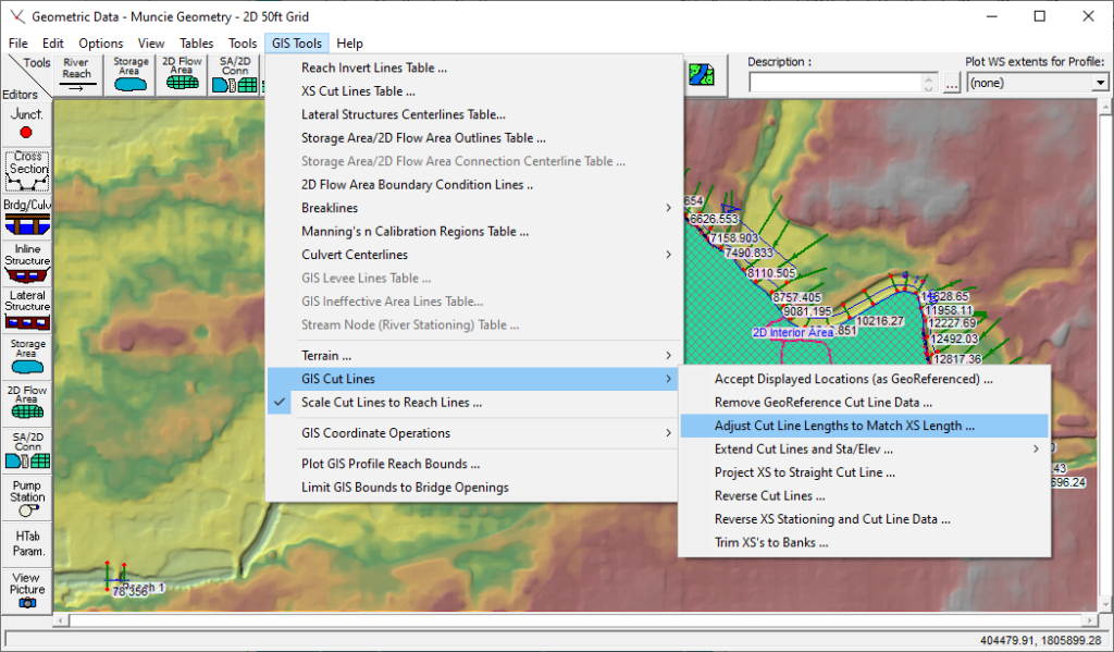
If your model contains numerous cross sections, this process can be quite time-consuming. Luckily, HEC-RAS does have a summary table that will allow you to perform this verification process more quickly. Navigate to a summary table that compares the modeled cross section length (XS length) to the GIS length (Cut Length) by navigating to the Geometric Data Editor. Then under GIS Tools, click GIS Cut Lines and Adjust Cut Line Length to Match XS Length.

The following table will appear. The Cut Length should be the same as the XS Length, resulting in a Ratio of 1.00.

What if the GIS length (Cut Length) of your cross sections does not match what is shown in the cross section data editor (XS Length)?
If the Cut Length does not match the XS Length as indicated by the red box in the image below, there are a few ways to fix it.

In many cases, the best way to address a mismatch between GIS cut line length and cross section length is to re-cut the sections that are off. This is easy if your model is georeferenced and contains the terrain data you would like to use for your sections. Simply click Cut from Terrain as shown in the image below.

Alternatively, you can adjust cross section lengths manually or by using the Adjust Cross Section Lengths tool as shown in the image below. However, changing cross section lengths can be tricky if there is no way to determine whether the previous modeler adjusted the left or right side of the cross section. In models where the first station is 0, determining whether the left or right side of the section was removed can be fairly simple. For example, if the first station of the problem section is greater than zero, the left side of the section was probably removed.

HEC-RAS Sections Are Not Showing
If your sections are not showing up in the Cross Section Data Editor and it is not a georeferenced model, try the following:
Step 1: Navigate to the Cross Section Data Editor. Then click GIS Tools -> GIS Cut Lines -> Remove Georeference Cut Line.
Step 2: The following box will pop up. Select the appropriate rivers and reaches from the dropdown menu. Then click the arrow in the middle. Finally, click Ok.

Step 3: Click GIS Tools -> GIS Cut Lines -> Accept Displayed Locations (as Georeferenced).