HEC-RAS allows users to define areas that contain water that will not be actively moving downstream. These areas are referred to as ineffective flow areas. Appropriately defining ineffective flow areas is an important part of the modeling process. However, representing ineffective flow areas in HEC-RAS models tends to be somewhat subjective in nature, and every modeler seems to have their own preferences and philosophies. The following article will describe how ineffective flow areas work in HEC-RAS and how they impact a hydraulic model.
Tip: I recommend adding ineffective flow areas only after developing a model that runs (e.g., start simple and add complexity). This is because ineffective flow markers can cause stability issues, especially with unsteady flow models, and it may be difficult to diagnose the problem if the modeler has added several ineffective flow markers initially.
What is Ineffective Flow?
Ineffective flow is a term used to define areas where water is not actively moving in the downstream direction. In HEC-RAS, ineffective flow areas are included in wetted perimeter computations and storage calculations. However, they are NOT considered when HEC-RAS performs conveyance calculations. This will become evident when comparing the top width (Top Wdth) and the actual top width (Top Wdth Act) in the Profile Output table. The top width refers to the width of the wetted cross section. In contrast, the actual top width refers to the top width of the wetted cross section, not including ineffective flow. Actual top width is the value HEC-RAS uses to perform its conveyance computations.
In HEC-RAS, ineffective flow areas are represented by diagonal green hatching in the Cross Section Data editor. It is worth noting that the concept of an ineffective flow area only applies to 1D hydraulic modeling. This is because HEC-RAS computes flow in all directions when running a 2D model, which eliminates the need for the user to add ineffective flow areas. However, when building a 1D hydraulic model, it is important to identify ineffective flow areas because HEC-RAS will not do it for you!
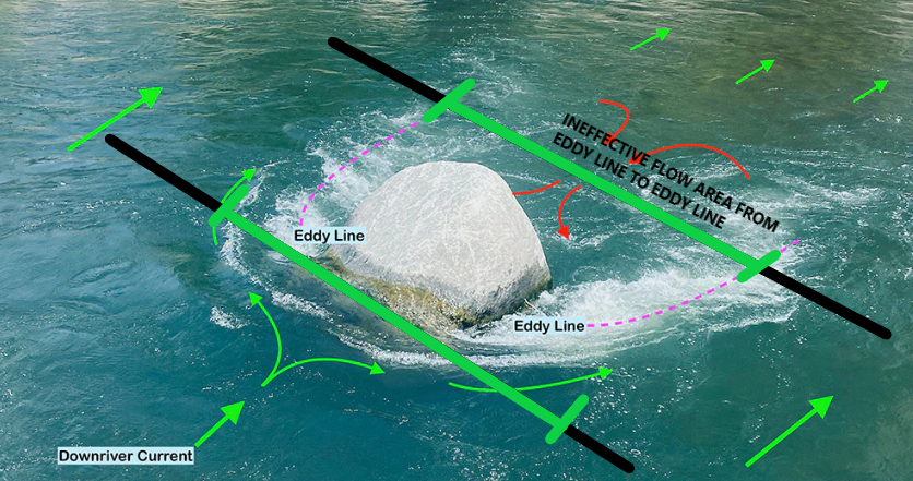
Typically, HEC-RAS users are most concerned with ineffective flow when adding a bridge to their model. However, ineffective flow areas can be used to represent other situations along a channel or river. For example, ineffective flow can be found when the flow goes around obstructions such as boulders in a channel. The image below is from the Cali Paddler website. Note that the water is not actively flowing downstream between the purple eddy lines. If cross sections, which are represented by black lines in the image below, were placed on the upstream and downstream sides of the boulder, ineffective flow markers would need to be placed on either side of the green lines. If these cross sections were part of a real HEC-RAS model, the area indicated by the green lines would not be included in the conveyance calculations performed by the program.
Adding Ineffective Flow Markers To Your HEC-RAS Model
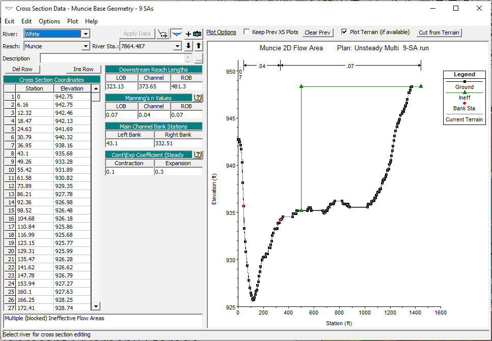
Ineffective flow areas are defined in HEC-RAS by adding “ineffective flow markers.” These markers represent the location of the ineffective flow area along the cross section. In addition, the user specifies the elevation at which flow becomes effective. The following section will describe how ineffective flow area data is entered into the HEC-RAS section. The images below show an ineffective flow marker that has been added to the right overbank of a cross section.
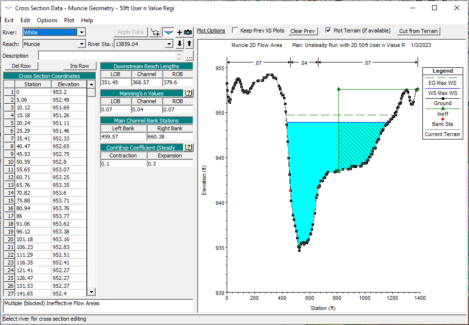
The image below depicts a cross section with an ineffective flow marker after the model is run. Note that the water surface elevation is the same across the entire cross section. Although the ineffective flow area is not considered when calculating conveyance, it is still depicted as having the same water surface elevation as the actively flowing portion of the section.
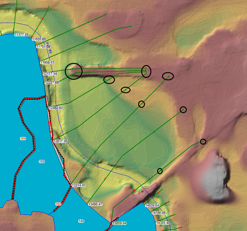
HEC-RAS also indicates ineffective flow markers in plan view with triangles that can sometimes be difficult to see. The black circles in the image below indicate areas where an ineffective flow marker has been added.
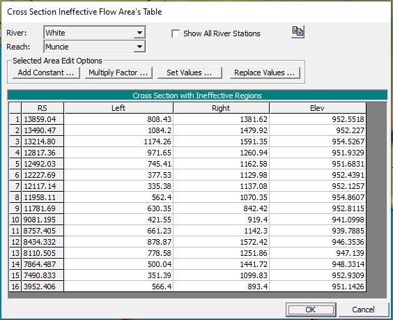
The table below lists all the cross sections that have ineffective flow markers along with the corresponding stations and elevations. This table can be found by navigating to the Geometric Data Editor. Then click Tables –> Ineffective Flow Areas.
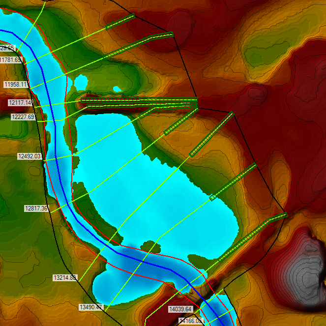
Ineffective flow areas are also shown in RAS Mapper as depicted in the screenshot below. Unlike the Cross Section Data Editor, ineffective flow areas are depicted as polygons in RAS Mapper. Users can add ineffective flow areas in RAS Mappers by right-clicking Ineffective Flow Areas and clicking Edit Geometry.
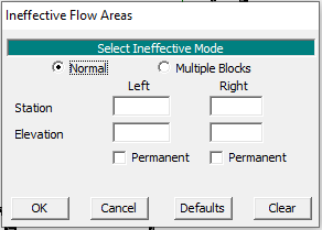
To add an ineffective flow area to a cross section, navigate to the Cross Section Data Editor, which can be found within the Geometric Data Editor. In the Cross Section Data Editor, select Options –> Ineffective Flow Areas. The dialog box below will appear. HEC-RAS then allows the user to enter the ineffective flow information in Normal mode or as Multiple Blocks. The Normal Ineffective Mode (see screenshot below) requires that the user enter a left and/or right station along with a corresponding elevation. When the user enters a left station, the program assumes the entire cross section to the left of the designated station is an ineffective flow area. Similarly, when the user enters a right station, HEC-RAS assumes that the entire cross section to the right of the designated station is an ineffective flow area. When the program calculates a water surface elevation that is below the elevation entered, it will treat the designated area as ineffective (it will not be counted in the conveyance calculations). Once the water surface rises above the elevation indicated, HEC-RAS assumes that the area can now convey water. However, if the user makes the ineffective area permanent, water will not be allowed to overtop the ineffective flow area.
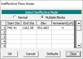
The Multiple Blocks mode allows the user to add up to ten ineffective flow areas within a cross section. Unlike the Normal Ineffective Mode, the user must enter a left station (Start Sta) AND right station (End Sta) for each ineffective area block. Users should also enter an elevation and indicate whether the ineffective flow area is permanent or not.
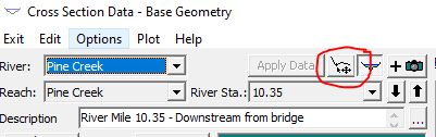
Users can also add ineffective flow areas in the Graphical XS Editor by clicking the icon shown in the image below. In the Graphical XS Editor, users can move existing ineffective flow area markers around. Additional ineffective flow areas can be added by clicking Options from the menu above.
Permanent Ineffective Flow Areas
As previously mentioned, permanent ineffective flow areas are not considered in HEC-RAS conveyance calculations regardless of the water surface elevation. Determining whether to select this option depends on a number of factors including the distance between the last cross section where there was ineffective flow and the structure that is causing the ineffective flow (e.g., a bridge or culvert). If the cross section is very close to the structure (bridge/culvert), it is probably reasonable to assume that the ineffective flow area is permanent. For example, flow against an abutment will always be ineffective because water cannot be conveyed through the concrete of an abutment. In that area, the water will only become effective once it goes over the bridge deck.
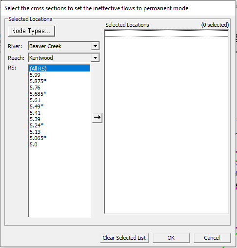
If it becomes necessary to make multiple cross sections’ ineffective flow area permanent, consider using the Ineffective Areas – Permanent Mode tool. This can be accessed by navigating to the Geometric Data Editor. Select Tools –> Ineffective Areas –> Set to Permanent Mode. Then simply select the cross sections with ineffective flow areas that need to be changed to permanent, click the area, and click OK. Note that there is no tool to set multiple cross sections back to non-permanent.
Ineffective Flow To Represent Overbank Storage Or Backwater
Ineffective flow markers in HEC-RAS can also be used to represent areas of overbank storage. Overbank storage, which is also called off line storage, is an area adjacent to the main channel in which water ponds rather than continuing to flow downstream. In some cases, these areas are represented by adding a “Storage Area” element to the hydraulic model. However, overbank storage areas can also be represented using ineffective flow markers. It is important to note that the water surface elevation within a cross section containing an ineffective flow area that represents overbank storage is assumed to be the same as the portion of the section that is actively flowing downstream. A levee marker (along with an ineffective flow marker in some cases) should be used to represent situations where the overbanks will not fill up before the banks are overtopped.
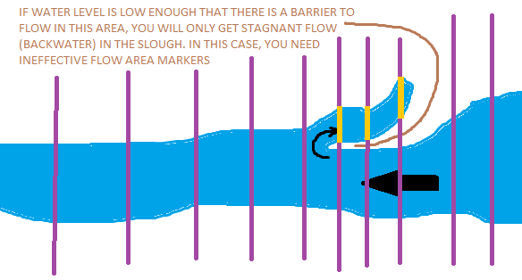
A similar situation occurs when modeling a backwater slough. A slough is a side channel from a river that is only sporadically filled with water. In such a case, there might be a barrier of high ground that prevents flow from entering the slough if the water level is low enough (see image below). In this case, use Multiple Blocks to add this ineffective flow area (yellow in the image below) to represent the backwater slough. Once the water is higher than the barrier, this area may begin conveying flow downstream. To ensure this is represented properly in a model, adjust the elevation accordingly and ensure the ineffective flow area is not marked as permanent.
Ineffective Flow at Bridges
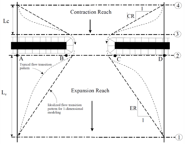
Ineffective flow is an important aspect of modeling bridges because flow contracts upstream of the bridge in order to squeeze through the bridge opening and then expands downstream as shown in the image below, which was obtained from the HEC-RAS Manual. The area outside of the black dashed lines (contraction and expansion zones) is ineffective and is not actively flowing downstream.
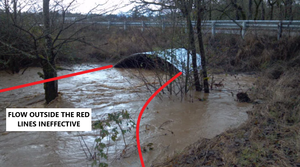
This concept is depicted more clearly in the image below, which shows ineffective flow at the downstream end (expansion) of a culvert. The flow outside of the red lines is ineffective.
The rule of thumb is to assume a contraction rate of 1:1 and an expansion rate of 2:1. This accounts for that the fact that flow tends to contract more efficiently upstream than it expands downstream because the flow is slower downstream. For this reason, the contraction zone tends to be shorter than the expansion zone. It should be noted that these ratios are only a rule of thumb, and flow behaves differently at different bridges. Ideally, the modeler would have the opportunity to observe flow at the bridge and take some photographs before developing a model to represent flow conditions at the bridge being modeled. Often, that is not realistic. In those cases, it is considered acceptable to assume a contraction rate of 1:1 and an expansion rate of 2:1 unless there is a rationale for using different values. Flow outside of these contraction and expansion zones is ineffective. In most cases, the flow will become effective/active once it overtops the bridge deck. Modelers can account for this by specifying the appropriate elevation at which that area begins to convey flow downstream as discussed in a previous section.
When adding an ineffective flow area at a bridge, start with an upstream elevation that is 0.5 to 1 foot above the high chord on the upstream side. On the downstream side, start with an elevation that is 0.5 to 1 foot below the high chord on the downstream side. Then run the model and verify that the flow distribution is consistent on both sides and adjust accordingly. This process will be described in further detail in the next section.
Checking Flow Consistency
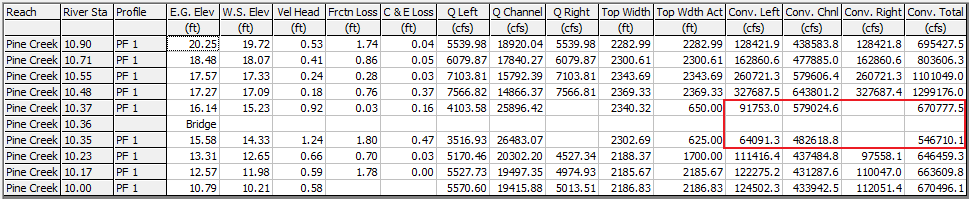
While this may sound simple and concrete, applying ineffective flow areas to properly represent flow at bridges is often an iterative process. This is because it is important for the flow distribution to be consistent at the upstream and downstream sides of the bridge. For example, in the table below, the left overbank conveys 13.7% of the flow on the upstream side and 11.7% of the flow on the downstream side. Similarly, the main channel conveys 86.3% of the flow on the upstream side and 88.3% of the flow on the downstream side. The conveyance in the left overbank, main channel, and right overbank is similar. To view these values, click Options –> Define Table in the Profile Summary Table dialog box. Then click a blank column and use the search bar to find Conv. Left, Conv. Chnl, Conv. Right, and Conv. Total. Add these column headings and click Ok. Finally, save the table by clicking Options –> Save Table. Otherwise, this information will disappear if the user clicks out of the Profile Summary Table.