HEC-RAS is a fantastic resource. While most hydraulic modeling software programs are expensive, HEC-RAS is freely available. However, the low (or lack of) price tag does not diminish its value to the industry. Many brilliant engineers have spent many years (some even decades) making this program what it is today. The program has been updated several times, and there are many features available today that were not around when I started my career (e.g., 2D modeling, RAS Mapper, etc.). While HEC-RAS has become more powerful and user-friendly over the last several years, new modelers may find building a HEC-RAS model from scratch somewhat daunting. The program has a deceptively simple interface, but it can take several years to truly master HEC-RAS.
1. Thoughtfully Space HEC-RAS Sections
When preparing a one-dimensional (1D) HEC-RAS model, it is important to thoughtfully place cross-sections at locations representative of the channel geometry in the vicinity. Additional sections should also be placed at locations with a change in cross-section size (wider or narrower), discharge, or velocity. It is also important to consider channel slope when adding cross sections to your model. Steeply sloped channels require more cross-sections than mildly sloped channels.
2. Start Simple and Build Complexity
When building an HEC-RAS model, building the whole thing and then pressing run when finished can be tempting. However, I’ve found it’s best to start simple, change a few things, and run the model. This will minimize the amount of time you spend chasing the source of errors. What does this look like in practice? When building a two-dimensional (2D) HEC-RAS model, for example, I start by outlining the study area, generating a mesh with a large pixel size, and running the model with a longer run time. This initial run gives me a better understanding of the overall drainage patterns and where I need to add mesh refinements.
3. Remember That 1D Manning’s n Values Are Not the Same as 2D Manning’s n Values
The Manning’s n value is often described as a “roughness coefficient.” In reality, this coefficient is a catch-all to account for energy loss from several factors that would be difficult to quantify individually (e.g., channel roughness, meandering, flow obstructions, vegetation, and contraction/expansion from channel cross-section irregularity). Manning’s n is used in both the 1D and 2D equations in HEC-RAS. However, it would be incorrect to say they are the same. This is because the 2D equations (St. Venant) account for energy losses that aren’t calculated in the 1D equations. For this reason, Manning’s n values in a 2D model will tend to be lower than those in a 1D model. How much lower? It depends on the complexity of the flow paths and other site-specific conditions, but 2D Manning’s n values are typically 15% to 25% lower than 1D Manning’s n values.
4. Effectively Use Breaklines in 2D Modeling
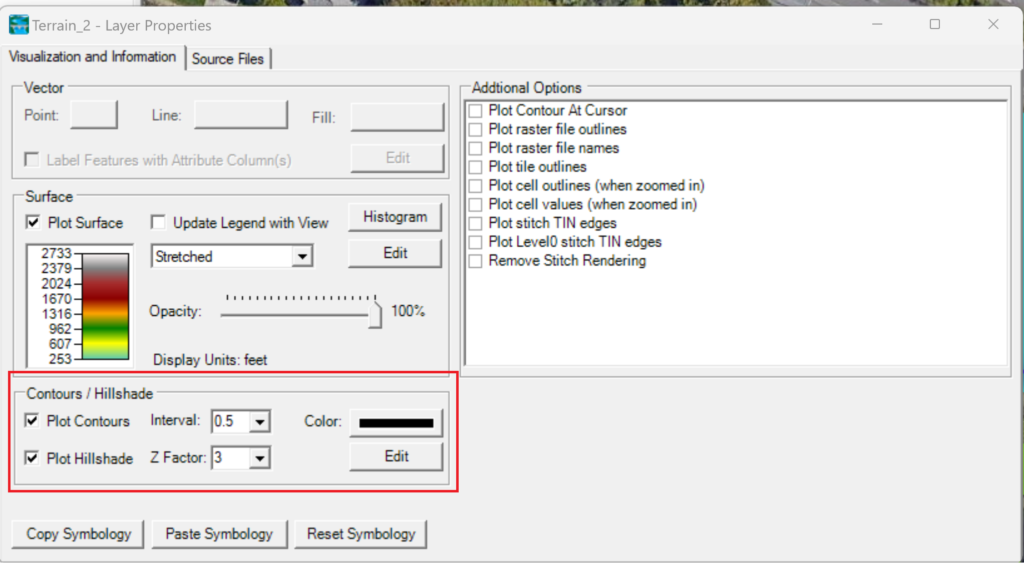
HEC-RAS 1D models cannot account for divided flow (e.g., flow on both sides of a high point/ridge). Some workarounds for this issue include the use of ineffective flow areas or lateral structures. Similar to an HEC-RAS 1D cross-section, HEC-RAS cannot account for divided flow at a given cell face. The program will simply allow flow through the lowest point of the cell face regardless of the presence of a ridge or high point. This is why breaklines are essential for 2D models. Breaklines are a tool used in 2D modeling to force cell faces to follow a ridge, roadway, or crest. They are important because they prevent modeled flow from going over (when it shouldn’t) or through high points in the terrain. This is a good alternative to reduce cell size because it prevents long run times. In HEC-RAS, you can draw your breaklines manually or import them as shapefiles. I like to draw breaklines by hand. I find this to be more accurate because it allows me to use the high-resolution contours in RAS Mapper. To turn on high-resolution contours, simply right-click your terrain dataset. Then select “Image Display Properties.” Then reduce the contour interval as low as necessary.
If your terrain is choppy or inaccurate along a known ridge, you can convert this breakline into a 2D/SA Area Connection. Simply eliminate terrain imprecisions for the Weir/Embankment Station/Elevation table.