Although HEC-RAS allows users to add structures to two-dimensional (2D) hydraulic models, adding structures can create instability issues within your model. It’s for this reason that modelers may choose to remove bridge decks. This is appropriate when the modeler is not interested in evaluating detailed bridge hydraulics.
In some cases, Light Detection and Ranging (LiDAR) data will be processed in such a way that the bridge decks and culverts are excluded. However, this is often not the case. Depending on how you would like to represent a bridge or culvert in your model, you may choose to simply “burn” the bridge deck out of the terrain. The following blog post will describe how to remove a bridge deck from terrain data for the purpose of eliminating an artificial impediment to flow since the bridge deck is not a solid mass that obstructs the entire stream. The result will look something like the screenshot below.
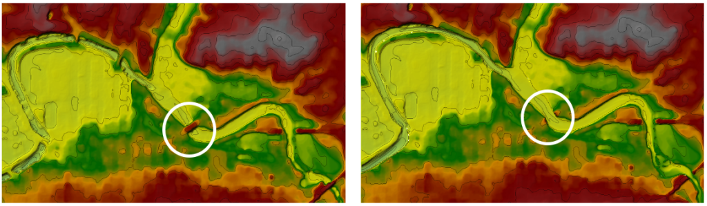
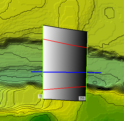
The images above depict terrain layers in RAS Mapper. The image on the left shows terrain data where the bridge deck is obstructing channel flow, which is not representative of reality. The image on the right shows terrain data that has been processed in RAS Mapper to remove the bridge deck from the channel. When the 2D model is run with the terrain dataset on the right, water will be free to flow through the channel rather than being blocked by the bridge.
Steps to Removing Bridges and Culverts from HEC-RAS Terrain Data
As previously mentioned, LiDAR data typically does not typically depict the actual terrain below the bridge deck. Fortunately, modelers can use RAS Mapper to quickly process their terrain data and remove these bridge decks. Overall, this process involves creating a terrain model that interpolates between two cross-sections placed upstream and downstream of the bridge. The interpolated surface is then combined with the original terrain dataset to generate a new terrain.
Step 1: Create a New Geometry in RAS Mapper
Firstly, turn on the Geometry layer and create a new geometry in RAS Mapper. Do this by right-clicking Geometries and clicking Add New Geometry as shown below. Then enter a name for your new Geometry file.
Step 2: Create a River Across the Bridge or Culvert
Secondly, expand your Geometry data and right-click Rivers. Then click Edit Geometry and draw the channel centerline. This centerline should extend a little bit beyond the upstream and downstream ends of the bridge.
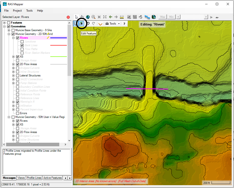
Note that the image below shows editing tools available in RAS Mapper. You can modify your River placement by clicking the button with the black arrow (see the circle in the image below). Then double click the channel and move the nodes as needed.
Step 2: Add Cross Sections on the Upstream and Downstream Sides of the Bridge or Culvert
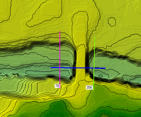
Similarly, right-click XS and then Edit Geometry to add cross-sections to the upstream and downstream sides of the structure. Draw the cross-sections left to right looking downstream. HEC-RAS will automatically number the sections. Finally, right-click the geometry name in the contents window of RAS Mapper, click “Stop Editing,” and save your edits.
Step 3: Define Bank Stations
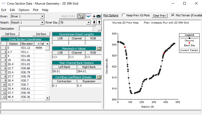
Next, exit out of RAS Mapper and navigate to the Geometric Data Editor. Then open the Cross Section Data Editor and define the Left Bank and Right Bank. Place the bank station at the beginning of where the terrain data is no longer accurate due to the bridge deck.
Step 4: Export the Geometry to a GeoTiff
When you have completed all editing, navigate back to RAS Mapper. Then right-click the geometry file name in the contents window of RAS Mapper and click Export Layer then Create Terrain GeoTiff from XS’s (Channel Only). You can also create a terrain model from the channel and overbank area. However, if you have decent terrain data, this is not recommended. Once you have selected the appropriate export option, a file dialog box will appear. Save your new terrain model in a folder that will be easy to find later. Then HEC-RAS will create an interpolated surface.
Step 5: Create a New Terrain Layer
Finally, create a new Terrain Layer by merging the Interpolated Surface exported in Step 4 and the original surface. To generate this combined terrain dataset, navigate to the top of the RAS Mapper menu bar and select Tools –> New Terrain. In HEC-RAS version 6.2, select Project –> Create New RAS Terrain. Click the “+” button and navigate to the base terrain dataset in the file directory. Then click “+” again to navigate to your interpolated terrain dataset. It is important the interpolated surface generated in steps 1-4 has a higher priority than the base terrain model. In other words, it should be listed first in the dialog box. Finally, press Create and the program will generate a merged terrain layer.
.