The purpose of a pump is to add energy to a fluid (water in the case of a rainwater harvesting system) such that the water leaving the pump has more energy than the water entering the pump. In this way, pumps make it possible to collect rainwater in a tank and use it for drip irrigation, high-pressure sprayers, sanitation systems, or convey it to an elevation that is higher than the tank. This article will describe how to select a pump for your rainwater harvesting system.
How Pumps Work
Pumps are often selected based on the flow rate (gpm). This is because pumps are designed to deliver a specific water flow (gpm) at a given pressure (ft or psi). However, pressure is affected by things such as friction loss and elevation. The following video provides an overview of how pumps, in general, work.
Types of Pumps
Before selecting a pump for your rainwater harvesting system, it is important to understand basic terminology, calculations, and the types of pumps available. A pump system refers to the water pump, control system, and other components that enable the pump to fit in with the rainwater harvesting. Technically, a water pump does not include the motor that drives the pump. However, the term “pump” is often used to refer to the pump and motor.
Pump Classification Based On Pressure And Flow
Pumps can be classified into those that produce higher pressure and lower flows and those that produce lower pressures and higher flows.
Transfer Pump – produce high flows at lower pressures. These pumps are appropriate for projects where the primary purpose of the pump is just to move water.
Pressure Pump – produce higher pressures and lower flows. These pumps are appropriate for projects that require a specific pressure at the point of use.
Pump Classification Based On Flow Through Impellers
The most common pumps, in general, are rotating impellers or reciprocating pistons. Other types of pumps include a progressive cavity, diaphragm, rotary-lobe, gear, roller, and peristaltic. However, impeller pumps are the most commonly used in rainwater harvesting. Impeller pumps are commonly known as either centrifugal, propeller or turbine pumps. The following list describes how impeller pumps are classified based on flow.
Radial – Water enters the pump at the center of the impeller and moves through the impeller perpendicular to the axis of rotation. Centrifugal pumps have radial flow.
Axial – The fluid enters and exists in the impeller parallel to the axis of rotation. The flow in propeller pumps is axial.
Mixed – Fluid leaves the impeller at an angle between radial and axial. Most turbine pumps have mixed flow.

Other Pump Definitions
Surface Pump – located outside of the tank.
Centrifugal Pumps – Uses an impeller connected to a motor to accelerate liquid into the discharge nozzle. In this way, they convert rotational kinetic energy into hydraulic energy. These pumps create a small region of low pressure at the eye of the impeller, which allows atmospheric pressure to push water into the pump. Centrifugal pumps are the most common type of surface pump.
Submersible Pump – immersed underwater near the bottom of the tank. These pumps use pressure to force water up to the surface and then to the end use. These pumps will take up less space than a surface pump.
Inline Pump – a pump that is installed into the pipe system the pump is serving.
Close Coupled Pump – a style of centrifugal pump that is characterized by the motor shaft and pump shaft being rigidly connected in a pump casing. The pump casing is bolted to the drive flange rather than being installed on pump feet. This style of pump is designed to save time and hassle by eliminating separate couplings and frame mounts that require tedious alignments.
Pump Anatomy
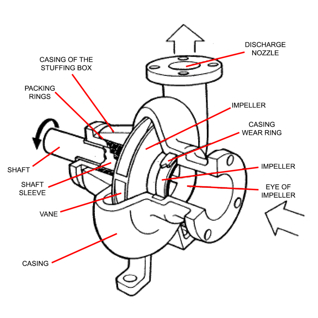
The most common type of pump used outside of a rainwater harvesting system is a centrifugal pump. Centrifugal pumps cannot be submerged. Most pumps you come across in daily life are centrifugal pumps. This is because they produce a large output for a given pump size, are reliable, and have a simple construction. Some key parts of a centrifugal pump are shown in the image below.

Diffusor – set of stationary blades surrounding the impeller. This is where kinetic energy is converted to pressure energy.
Discharge Nozzle – where fluid exits the pump
Impeller – part of the pump that moves water inside of a centrifugal pump
Inlet – the center of the pump impeller
Involute/Eye of Impeller – moves water inside of a centrifugal pump
Motor – provides the force to move fluid through the pump. Electric motors typically drive permanently installed pumps. Gas or diesel-powered engines can be used to power portable pumps.
Multi-Stage/Variable Speed Pump – Contain two or more impellers arranged in series which allows the pump to operate at a wide range. This is useful for systems that require a range of flow rates and pressures.
Priming – the process in which the impeller of a centrifugal pump is fully submerged in the fluid which is to be transferred with no air trap inside. Priming should occur prior to the pump’s startup.
Self-Priming Centrifugal Pump – designed to lift water from a level below the liquid to be pumped without having to fill the suction piping with liquid. This is accomplished by creating a partial vacuum at the pump suction that evacuates air from the suction line.
Stuffing Box/Packing Box – the space within the interior of the pump casing where the shaft pierces the physical barrier separating the pumping side (e.g., impeller and volute chamber) that is in direct contact with the water being pumped from the power side of the pump (e.g., packing box/stuffing box).
Volute vs Diffuser Pumps
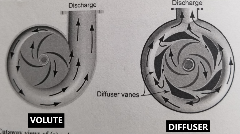
Pumps are classified as either volute or diffuser depending on the construction of the casing around the impeller. A volute-type pump has a casing that is spiral in shape. Diffuser-type pumps have stationary guide vanes surrounding the impeller.

Pump Selection Considerations
Rainwater harvesting designers should consider the following when sizing and selecting pumps for their system.
- Will you use a surface pump or a submersible pump?
- Is the pump elevation appropriate? Is there enough net positive suction head (NPSH) to prevent cavitation?
- What controls are needed (e.g., switches, backflow prevention, valves, etc.)?
- How will the pump be mounted?
- Manufacturer instructions for pump installation, operation, and maintenance.
- Electrical point of connection.
- Site pressure requirements/final pressure needed at the point of use (see the following section).
- Maximum flow rate (gpm) required.
Many of the considerations listed above are connected. For example, it is important to consider how electrical service will be provided to the pump motor when determining a mount location. In this way, pump sizing and selection can be an iterative process.
Site Pressure Needs
When selecting and sizing a pump, it is important to understand how much pressure is required for a specific site’s rainwater harvesting system. Pumps are required for rainwater harvesting systems when they are being used for drip irrigation, for conveying water to higher elevations, for domestic water supply, or when the flow is being conveyed through a disinfection system.
When selecting a pump, it is important to understand the total dynamic pressure head (TDH) needed at the pump discharge point during maximum flow. The total dynamic pressure head is calculated using the equation below. It is important to note that 2.31 psi is equal to one foot of head.
TDH = Static Head + Final Pressure Head + Friction Loss + Suction Head
where,
Static head (sometimes referred to as discharge or delivery head) is the vertical distance between the pump outlet and the highest water surface in the tank (ft).
Final pressure head is the pressure required at the final point of use during maximum flow (ft).
Friction loss is the reduction in pressure due to friction (at maximum flow) through the pipes and associated elbows, bends, and valves (ft).
Suction head/suction lift is the vertical difference between the pump inlet and the water surface elevation. Only applies if the pump is at an elevation higher than the pump inflow (e.g., an underwater tank). Friction loss in the suction pipe should also be taken into account (ft).
The table below lists typical pressure requirements for common end uses of rainwater harvesting systems. Please note that this table is meant to serve as a guideline, and it is important that designers verify their system’s needs and requirements.
| End Use | Pressure (psi) |
| Drip Irrigation | 15 – 25 |
| Pressure Washer | 20 |
| Garden Hose | 35 |
| Water Purification, 0.5-micron pore size | 30 – 50 |
After calculating TDH, select the proper pump size by examining the pump curve and identifying the point where the TDH and desired pump capacity intersect. If the point of intersection falls above the pump curve, try a larger pump. For example, if we are looking at the pump curves below to select a pump with a capacity of 15 gpm, and we calculated a TDH of 150 feet, we would select Model AB for our system.

Curves Used for Pump Selection
The capacity and head requirements of the irrigation system should be determined before selecting a pump. The designer should select a pump that matches the head-capacity characteristics of the irrigation system and water supply (rainwater harvesting tank). This becomes more complicated when the flow requirements for the system vary. The pump selected should cover a full range of conditions (lowest flow rate to highest flow rate) and the highest total dynamic pressure head (TDH). Low flow rates can cause pumps to start and stop during an irrigation cycle, which causes excessive wear on the pump. Excessive flow demand can cause cavitation.
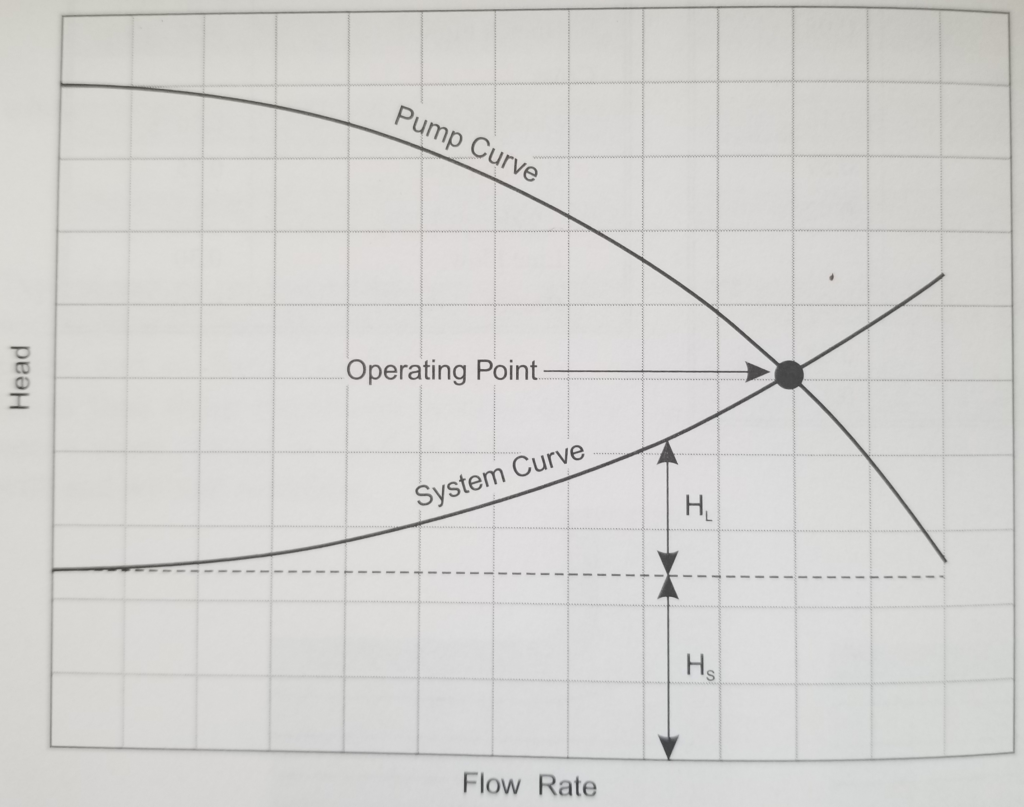
The goal in selecting a pump is to find one that will operate at or near its highest efficiency. You can determine this point by plotting the head-capacity curve for the pump (pump characteristic curve) and the head-capacity curve for the system (system curve). The system curve, which is different for every project site, will shift vertically depending on the depth of water in the tank.
Pump Characteristic Curve (Pump Curve) – The pump characteristic curve describes the interaction between pressure (head) and flow. When a pump is placed at a higher elevation (more head/pressure), it will pump water at a lower flow rate. Thus, maximum delivery pressure occurs when there is no flow (the pump outlet is closed). The characteristic curve is typically determined by the manufacturer through precise testing. The system should operate below the pump curve, which means that the pump curve should exceed the ranges of flow rate (Q, gpm) and H (head, ft) needed to operate the irrigation system.
System Curve – As previously mentioned, the system curve is different for every rainwater harvesting project site. The system curve can be generated by calculating head loss/friction loss (HL) at various flow rates using the Hazen-Williams equation and adding those values to the static head (HS). The system curve will shift vertically with variations in tank water level. For this reason, high and low system curves should be developed to ensure that the pump can function within the full operating range.

Pump Efficiency Curve – the efficiency of a pump represents the portion of the mechanical energy delivered to the pump shaft that is transformed into hydraulic energy as shown in the equation below.

where,
BP is brake power in HP,
WP is water power in HP,
Ep is pump efficiency,
Q is discharge (gpm), and
H is total head (ft).
A significant amount of the input energy is lost to friction inside of the pump. Under favorable conditions (a well-designed pump system), pump efficiencies should be 70% or greater. In contrast, under unfavorable conditions, pump efficiencies can be as low as 20% (Huffman et al., 2013).
Pump Duty Point/Operating Point – The point where the pump characteristic curve and the system curve intersect. Changes to the system (e.g., a valve opening) will affect the system curve, and thus, move the duty point. Similarly, a change in the pump curve (e.g., worn impeller) will also result in the duty point moving. It is possible to trim the impeller to optimize the duty point. For this reason, you may see multiple pump curves for a single model of pump.
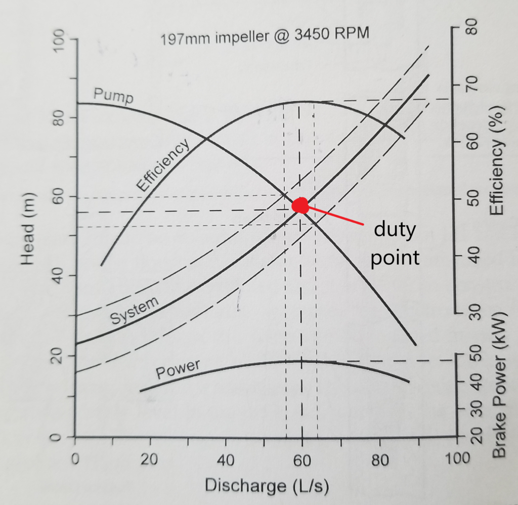
Example of combining pump performance curves
The image below is an example of combining some of the curves discussed above. In practice, it would be very rare to find a pump that fit the desired conditions so perfectly. However, you could shift the pump curve down and to the left by altering the pump speed or trimming the impeller. There are variable speed drives and load-sensing controls available to automatically adjust pump speed based on changes to the system. Variable-speed drives are more expensive than fixed-speed drives, but the cost could be justified if the increased efficiency resulted in cost savings.

Code Requirements
According to ARCSA/ASPE/ANSI 63-2013:
The pump shall be capable of delivering a minimum of 205 kPa (15 psig) residual pressure at the highest and/or most remote outlet served. The minimum pump pressure shall allow for friction and other pressure losses. The maximum pressure shall not exceed 653 kPa (80 psig). A pressure-reducing valve shall be provided at water branch distribution piping if the pump is capable of exceeding 618 kPa (75 psig).
psig = pounds per square inch gauge
Avoiding Cavitation
Cavitation is one of the most significant hazards to a pump. Cavitation occurs when the pressure drops below saturated vapor pressure. As a result, pockets of water vapor form rapidly and implode inside of the pump. Suction cavitation occurs when pump suction is under a low-pressure/high vacuum condition and the liquid turns to vapor inside of the eye of the pump impeller. Cavitation can cause noise, vibration, and structural damage to the pump impellers.
To prevent cavitation, there must be enough pressure at the inlet of the pump to push water into the pump without dropping the water pressure to the point where cavitation occurs. Suction lift, which refers to the vertical difference between the pump inlet and free water surface, should NOT be higher than the total energy available on the inlet side of the pump. The equation below allows you to compute the maximum practical suction head.

where,
NPSHa is the maximum practical suction lift/actual net positive suction head available (ft),
Hatm is the atmospheric pressure at the free water surface (ft)
Hf is inlet-side friction losses (ft),
es is the saturated vapor pressure of the water (ft),
NPSHr is the net positive suction head required (ft),
Fs is a safety factor (2 ft).
NPSHr is a characteristic of the pump and is determined by the manufacturer. NPSHr represents the energy at the inlet (suction side) of the pump that is required for the pump to function. It should be noted that NPSHr increases as pump discharge increases. For safe operation, NPSHa should be greater than NPSHr. It is important to apply a safety factor to the equation above because friction losses will increase over time due to debris accumulation on the intake screen and pipe friction increasing with age. This increase in friction can lead to failure by cavitation.
One of the most common causes of cavitation is putting the pump in a spot that is too far above the tank’s water surface elevation. If possible, it is best to put a surface pump at the same elevation as the bottom of the tank. This creates a condition referred to as flood suction.
Flooded suction – a condition where the suction port of a surface pump is flooded with water by gravity. A submersible pump placed inside of a tank will always have flooded suction unless the suction port is blocked by debris or the tank runs out of water.
Vibration can also contribute to cavitation in pumping systems. For this reason, it is important to properly align drive components to minimize vibration.
Priming A Pump
Centrifugal pumps, unless explicitly stated, are generally not self-priming. Self-priming pumps are available, but they can have lower efficiencies. Submersible pumps are designed to operate underwater and do not need priming after installation.
To prime a pump, the suction line and pump should be nearly full of water. You can do this by manually filling the pump with water or removing air with a suction pump or an engine exhaust primer. A gate valve on the discharge side of the pump and a check valve at the lower end of the suction line are important for priming a pump (except at low suction heads).
Electrical Connection
If the pump for a rainwater harvesting system comes without a plug for easy electrical connection, an electrician is needed to carry out the connection in accordance with local requirements. The mains voltage and frequency shown on the pump nameplate should be compared with the electrical supply available. This is because some flow rates and pressures require higher voltage and three-phase power. For most residential rainwater harvesting systems, 115V/1 phase/60 Hz or 230V/1/60Hz power is sufficient.
It should be noted that for three-phased pumps, the direction of rotation should be checked every time the pump is connected to a new system.