Boundary conditions are an important part of hydraulic modeling as they allow hydraulic modeling programs such as HEC-RAS to begin performing water surface profile calculations. In HEC-RAS, users enter boundary conditions in the Steady Flow Data Editor and the Unsteady Flow Data Editor.
The following article is an introduction to applying boundary conditions in HEC-RAS and includes a description of each boundary condition option available in HEC-RAS.
Water Surface Profile Computations in HEC-RAS (Steady Flow Analysis)
To understand how boundary conditions work in HEC-RAS, it is important to understand how water surface profile calculations are performed in HEC-RAS. In HEC-RAS, one-dimensional (1D) steady-state flow computations are based on the energy equation shown below.
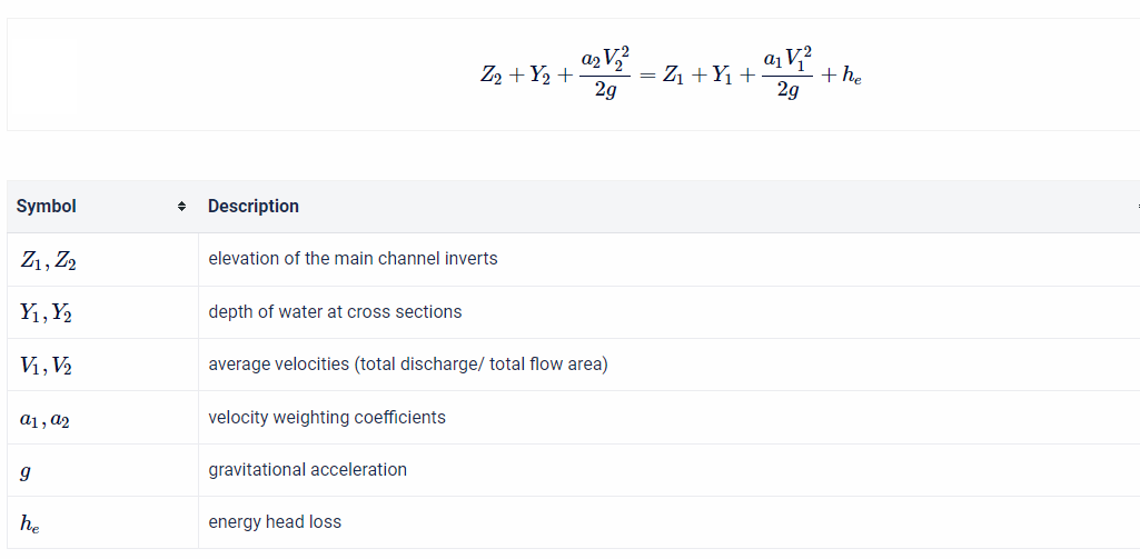
The steps involved in calculating subcritical flow water surface elevations for each cross-section are listed below.
- The discharge/flow rate for which the water surface profile calculations will be performed is selected.
- Channel and cross-section geometry are defined.
- A water depth at the downstream end (Y2) is selected.
- For the Y2 value selected in Step 3, velocity, conveyance area, and other hydraulic parameters are calculated.
- A water depth at the upstream end (Y1) is assumed.
- For the Y1 value selected in Step 5, velocity, conveyance area, and other hydraulic parameters are calculated.
- The energy loss between sections 1 and 2 is calculated
- The energy equation is solved. If the energy equation is not balanced, a new Y1 is chosen. Then Steps 5 through 7 are calculated until the energy equation is balanced.
- This process then moves one section upstream.
The process for calculating supercritical flow water surface elevation is applied similarly. However, the computations move in the downstream direction rather than the upstream direction.
Entering Boundary Conditions for a Steady Flow Analysis
For steady flow analyses, boundary conditions are required to establish a water surface elevation at the ends of each river reach. HEC-RAS can then begin to perform one-dimensional (1D) water surface profile calculations.
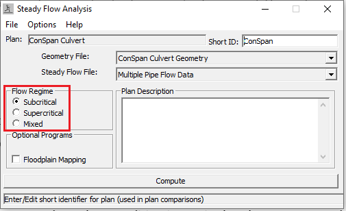
As shown below, you can run a steady flow analysis as subcritical, supercritical, or mixed. Depending on what flow regime you select, you will be required to enter an upstream boundary, a downstream boundary condition, or both.
Subcritical Flow Regime
Subcritical flow occurs when the water depth is greater than critical depth and the Froude number (Fr) is less than one. Subcritical flow can be described as “tranquil flow” as it tends to be characterized by low velocities and greater depths. The subcritical flow regime is commonly applied to floodplain models and models representing natural rivers. When running an HEC-RAS model with the subcritical flow regime, the user is only required to enter a boundary condition at the downstream end of each river reach. This is because subcritical flow calculations move upstream. As a result, changes in channel geometry, slope, or flow can affect the results of an HEC-RAS model for a considerable distance upstream.
Supercritical Flow Regime
Supercritical flow occurs when the critical depth is greater than water depth and the Froude Number (Fr) is greater than one. Supercritical flow can be described as “rapid” or “turbulent” as it is characterized by high velocities and shallower water depths. Supercritical flow is not common in natural rivers. However, it is more common in manmade channels and in curb and gutter systems. When running a model in the supercritical flow regime in HEC-RAS, a boundary condition is required at the upstream end of each river reach. This is because supercritical flow calculations move downstream. As a result, changes in channel geometry, slope, or flow can affect the results of an HEC-RAS model for a considerable distance downstream.
Mixed Flow Regime
Because the mixed flow regime performs subcritical and supercritical calculations, you must enter boundary conditions for the upstream and downstream ends of each river reach. The mixed flow regime is appropriate for models representing stream reaches that contain hydraulic jumps. The following steps describe how the mixed flow regime is applied in HEC-RAS:
- First, a subcritical water surface profile is calculated based on the downstream boundary condition. During the subcritical calculations, all locations where the program defaults to critical depth are flagged for further analysis.
- Next, the program calculates a supercritical profile based on the upstream boundary condition assigned by the user. HEC-RAS then compares the specific force calculated for the subcritical profile and a specific force for the supercritical profile. If the subcritical calculations produce a greater specific force, HEC-RAS begins searching downstream to find a location where the program defaulted to critical depth in the subcritical run. When a critical depth is located, HEC-RAS uses it as a boundary condition to begin a supercritical profile calculation. When the program reaches a cross-section where the subcritical specific force is greater than the supercritical specific force, HEC-RAS assumes that a hydraulic jump occurred between that section and the previous cross-section.
- The program calculates a supercritical profile in the downstream direction until it reaches a cross-section that has both a valid subcritical and a supercritical answer. When this situation occurs, HEC-RAS calculates the specific force for both the subcritical and supercritical profile. HEC-RAS defaults to the profile associated with the answer that produces the greater specific force. If the supercritical answer has a greater specific force, HEC-RAS continues performing supercritical calculations in the downstream direction.
- The program then goes to the next downstream location that has a critical depth answer and continues the process.
Entering Boundary Conditions for an Unsteady Flow Analysis
Boundary conditions are entered a bit differently in unsteady flow analyses. This is because the unsteady flow analyses are based on the continuity equation and the momentum equation rather than the energy equation. Unlike a steady flow analysis, you can add internal as well as external boundary conditions to an unsteady flow model. External boundary conditions are required to run an unsteady model. These are the boundary conditions you must add to the upstream and downstream ends of each reach (or 2D flow area).
Internal boundary conditions are optional and allow the user to define gate operations and add flow within a river reach.
Flow hydrographs, stage hydrographs, and normal depth are the most commonly used boundary conditions for unsteady flow analyses.
Unlike a steady flow analysis, the user does not have the option to select a “flow regime” when performing an unsteady flow model in HEC-RAS. This is because the program automatically runs unsteady flow models in a mixed flow regime.
Boundary Conditions in HEC-RAS
Different boundary conditions are available for steady flow analyses and unsteady flow analyses. There are also several internal boundary conditions available for unsteady flow analyses. Each boundary condition option in HEC-RAS is summarized in the table below.
| Boundary Conditions | Upstream or Downstream? | Internal or External? | Steady or Unsteady? |
| Normal Depth | Both for steady, downstream for unsteady | External | Both |
| Critical Depth | Both | External | Steady |
| Known Water Surface Elevation | Both | External | Steady |
| Rating Curve | Both for steady, downstream for unsteady | External | Both |
| Stage Hydrograph | Both | External | Unsteady |
| Flow Hydrograph | Both | External | Unsteady |
| Stage/Flow Hydrograph | Both | External | Unsteady |
| Lateral Inflow Hydrograph | N/A | Internal | Unsteady |
| Uniform Lateral Inflow | N/A | Internal | Unsteady |
| Groundwater Interflow | N/A | Internal | Unsteady |
| Time Series Gate Openings | N/A | Internal | Unsteady (Gates) |
| Elevation Controlled Gates | N/A | Internal | Unsteady (Gates) |
| Navigation Dams | N/A | Internal | Unsteady (Gates) |
| Rules | N/A | Internal | Unsteady (Gates) |
| Internal Boundary Condition Stage/Flow Hydrograph | N/A | Internal | Unsteady (Inline Weir) |
| Precipitation | N/A | N/A | Unsteady (2D) |
Normal Depth
Normal depth is the most widely used boundary condition for steady and unsteady analyses. The user is required to enter an energy slope. HEC-RAS will use that value to compute depth using Manning’s equation. You can approximate the energy slope by measuring the slope of the reach downstream of your modeled reach.
Critical Depth
Applying the critical depth boundary condition may be tempting because the user is not required to enter anything. However, critical depth does not occur very often in streams or channels. Using critical depth is only appropriate if there is a significant elevation change or drop structure. That being said, it doesn’t matter if you use critical depth AS LONG AS your model extends far enough upstream or downstream of the area of interest.
Known Water Surface Elevation
The known water surface elevation boundary condition is typically based on observed data. Alternatively, you may enter a known water surface elevation if you want your model to be consistent with another existing model. Just make sure the water surface elevation you enter into your model is referenced to the correct vertical datum.
Rating Curve
A rating curve is a relationship between discharge and stage for a given point in a stream. Rating curve boundary conditions are typically used where a channel or stream flows into a pond or lake. You can construct a rating curve using data available on the United States Geological Survey (USGS) website. Alternatively, you can develop a steady-state model to produce a rating curve.
You should be careful when producing a rating curve because it can cause instabilities in your model. Avoid using rating curves with few points or abrupt changes. You should also avoid using looped rating curves, which are common in tidal zones where flow reverses, in your model.
Stage Hydrograph
A stage hydrograph is a relationship between stage and time. It is typically used as a boundary condition in the following situations:
- Tidal areas
- When modeling backwater conditions from another reach, lake, or pond.
- When modeling a specific storm event with observed historical data.
Flow Hydrograph
A flow hydrograph is a relationship between time and discharge. Use this boundary condition if you want to apply gage data or HEC-HMS output to your HEC-RAS model. You may also want to apply a breach outflow hydrograph as an upstream boundary condition in order to produce an inundation boundary.
Stage/Flow Hydrograph
A stage/flow hydrograph is a combination of a flow hydrograph and a stage hydrograph.
Lateral Inflow Hydrograph
A lateral inflow hydrograph is an internal boundary condition that can be applied at a specific location. The purpose of a lateral inflow hydrograph is to model a point discharge (e.g., a storm sewer) entering a stream. Apply lateral inflows one cross-section upstream of where they would be observed in real life.
Uniform Lateral Inflow Hydrograph
The uniform lateral inflow boundary condition allows the user to evenly apply a single flow hydrograph between an upstream and downstream cross-section. This boundary condition would be useful when distinguishing between runoff into the left overbank and runoff into the right riverbank. Please note this requires two uniform lateral inflow hydrographs. In general, applying one uniform lateral inflow hydrograph is more stable than applying multiple lateral inflow hydrographs.
Groundwater Interflow
A groundwater interflow boundary condition can be applied to a reach or a storage area. HEC-RAS allows groundwater to enter the reach and leave a reach or storage area.
The following information is required for a groundwater interflow boundary condition:
- Location (river station) of the upstream cross-section
- Location (river station) of the downstream cross-section
- Groundwater stage
- Darcy’s loss coefficient
- Distance between the groundwater stage and the river stage
HEC-RAS calculates groundwater interflow using Darcy’s equation. The algorithm is very simple. It only allows groundwater to flow in one direction (laterally and perpendicular to the river). The aquifer is assumed to be very large such that the exchange of water with the river has no impact on the groundwater level.
Time Series Gate Openings
The time series (T.S.) gate openings boundary condition is probably the simplest “gate boundary condition.” The user simply enters a gate opening height for each time step of the entire simulation period.
Elevation Controlled Gates
The elevation-controlled gates boundary condition is a little more complicated. The user must tell HEC-RAS when each gate will open and close as well as the opening and closing rates. Based on this information as well as the reference point, HEC-RAS will decide what the gate setting should be at a particular time step.
Navigation Dams
The Navigation Dams option is another boundary condition used for gates. This boundary condition option is used to maintain a minimum and maximum water surface elevation at a reference point by opening and closing gates. You may want to use the Navigation Dams boundary condition if you want to maintain a particular water surface elevation in a reservoir.
There are four optimization options available in HEC-RAS for Navigation Dams:
- Pool Only,
- Hinge Point Only,
- Hinge Point and Minimum Pool Operations, and
- Hinge Point and Minimum and Maximum Pool Operations.
The “Pool Only” optimization option is the simplest. It tells HEC-RAS to maintain a specified water surface elevation just upstream of the gate. Because there is a delay between the flood wave arrival and the water surface elevation change due to the gate setting, HEC-RAS must forecast a flow rate at the gate. The program does this by monitoring the flow rate at a user-specified location further upstream of the gate. It may take a couple of tries to find a good flow monitoring location. As an initial guess, the travel time between the flow monitoring location and the gate should be similar to the gate change time increment (Brunner, et al. 2010a).
Rules
The Rules boundary condition provides the user the opportunity to customize gate operations beyond what is available in the other gate boundary conditions options. For example, the user may set up a Rule that tells HEC-RAS to open or close a gate based on the flow at a specified reference point.
Internal Boundary Stage and Flow Hydrograph (IB Stage/Flow)
The Internal Boundary Stage and Flow Hydrograph (IB Stage/Flow) is an internal boundary condition that can be used at a cross-section immediately upstream of an inline structure in order to force a known stage and/or flow for part or all of a simulation.
It is worth discussing how the program handles IB Stage/Flow at inline structures with elevation-controlled gates. HEC-RAS will now operate the gates in order to produce the forced stage or flow. When the specified IB Stage/Flow “runs out,” HEC-RAS will resume normal gate flow.
An example of an Internal Boundary Stage and Flow Hydrograph (from the HEC-RAS User’s Manual) is shown above. In this example, HEC-RAS forces the stage to be 108 feet until the simulation begins. Then the program starts using the flow rates entered for the first two hours. After the first two hours, there is no more data entered, so the program will start solving for stage and flow.
Precipitation
The precipitation boundary condition can be used to apply rainfall to a 2D flow area. This is called “rain on-grid” modeling. This is a relatively new option in HEC-RAS. Rain-on-grid modeling is an exciting addition to HEC-RAS because allows the user to merge hydrologic and hydraulic modeling into one program. The following video was published by the Australian Water School. It is a great resource for those who want to learn more about rain-on-grid modeling.
Thank you for this informative article on HEC-RAS Boundary Conditions by Paige Brue. It provides a comprehensive overview of boundary conditions in HEC-RAS, both for steady flow and unsteady flow analyses. The detailed explanations and examples for each boundary condition option are especially helpful for those working with hydraulic modeling. This article serves as a valuable resource for understanding and applying boundary conditions effectively in HEC-RAS.
Great explanations!